Stress Distribution Examples
This section contains ten examples of typical stress distributions which have been evaluated using centre hole drilling at Stresscraft. Many of the examples show quite ‘ordinary’ results without any extreme stress magnitudes or gradients, but each shows how processes applied to the sample or part contribute to the final stress distribution and provide some insight into the ways in which the processes interact. Each example contains scales of stress and depth and a brief description of the example and processes.
Example 1 - Annealed titanium alloy disc:
A titanium alloy disc has been annealed following machining (turning) and subjected to centre hole drilling on an end surface using a 031-size gauge. Distributions of radial and circumferential stresses show the effectiveness of the annealing process with only small stresses remaining in near- and sub-surface material.
Example 2 - Machined nickel alloy disc - single gauge:
The figure below shows the distributions of meridional and circumferential stresses at a chamfer on a machined, nickel alloy disc forging. Sub-surface stresses (deeper than 100 microns) reveal moderate compressive meridional stresses and small circumferential stresses within the forging structure. Circumferential stresses are seen to increase sharply towards the machined surface, while the near-surface gradient of meridional stress is significantly smaller.
Example 3 - Machined nickel alloy disc - six gauges:
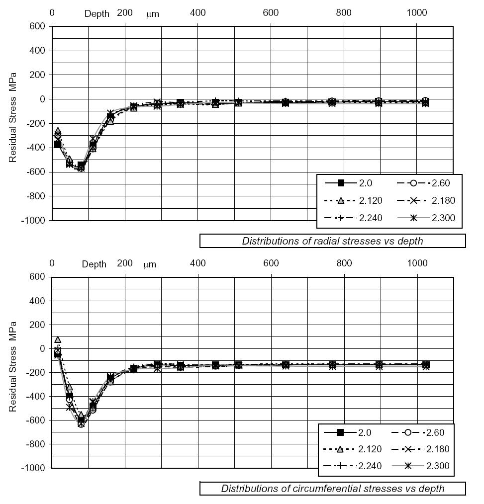
A machined nickel alloy forged disc has been subjected to centre hole drilling using 062-size strain gauges. Six gauges have been equi-spaced around the hub flank to measure overall stress levels, the depth of penetration of machining stresses and circumferential variation in stresses. Stress distributions at all gauges confirm the presence of moderate compressive sub-surface stresses within the forging and the characteristic machining stress profiles which extend to a depth of ~ 300 microns. Near-surface and sub-surface stresses show very low levels of circumferential variation.
Example 4 - Deep cold-rolled sample:
Distributions of stresses in a deep cold-rolled titanium sample are shown below. For this example, a 125-size gauge has been used to determine stresses to a depth of 2 mm. the distributions show significant differences in near-surface stress magnitudes in the longitudinal and transverse directions.
Example 5 - Shot peened nickel alloy sample:
A high strength nickel alloy sample has been shot peened. Centre hole drilling using a 031-size strain gauge shows extreme near-surface compressive stresses which decay to zero at a depth of ~180 microns. Thereafter, small, complementary tensile stresses are seen to occur over the depth range 180 to 350 microns.
Example 6 - Machined and shot peened steel alloy block:
A machined steel block has been subjected to a shot peening process. Centre hole drilling at a 031-size gauge confirms the presence of near-surface compressive stresses resulting from the peening process. In this case, significant compressive stresses resulting from the peening process have penetrated to a depth of ~150 microns, while the effects of the initial machining process remain visible over the depth range 150 to 450 microns.
Example 7 - Shot peened nickel alloy forging:
In this example, part of a forging has been shot peened and subjected to centre hole drilling (031-size gauge). Sub-surface axial stresses within the forging are seen to be compressive while circumferential stresses are tensile; differences in these stresses is around 700 to 800 MPa. The shot peening process produces near-surface compression in both axial and circumferential directions. The stress distributions show no significant residues from machining prior to shot peening.
Example 8 - Shot peened strip:
A thin alloy steel strip has been shot peened on both sides. One 031-size strain gauge has been applied to each side, offset longitudinally to avoid any detectable interference. Each gauge has been subjected to incremental drilling to ~ 50% of the strip thickness. Distributions of longitudinal stresses are seen to be substantially similar at the two gauges, with compressive stress maxima in the range -850 MPa to -950 MPa. Corresponding tensile stress maxima around the strip mid-thickness attain 600 MPa. While there is a small mis-match in distributions at the mid-thickness, the net area below each curve is close to zero, confirming the equilibrium of longitudinal stresses and moments.
Example 9 - Ex-service nickel alloy ring - twelve gauges:
In this example, twelve equi-spaced 062-size strain gauges have been applied to the bore of an ex-service ring component. Results from the gauges show generally similar stress distributions from the gauges with significant compressive stresses remaining from the peening process applied during manufacture. While the variability in near-surface axial stresses is, perhaps, greater than in corresponding circumferential stresses, there are no significant disturbances in sub-surface stress distributions.
Example 10 - Shot peen parameter study:
High-strength steel coupons have been shot peened with various peening parameters (shot-size, intensity, coverage, etc). A series of 031-size gauges has been installed and drilled. In the figure below, line ‘0’ refers to the as-machined condition while lines ‘1’ to ‘4’ show generally increasing levels of compressive stresses and depths of penetration achieved by varying the peening parameters.


